Rendering#
Introduction#
The Rendering phase creates the two images of the stereoscopic pair (or a single compound image) to be shown in some viewing device.
The main functions are:
- Apply Size Prescriptions
- Apply Horizontal Disparity Prescriptions
- Generate the image(s) in a size and format appropriate for the intended viewer.
Rendering requires:
- A .pair file that contains the necessary Angular Alignment parameters, and the identification of the original image files
- Original image files. If they are RAW it is searched a JPG child, that may be a developed JPG or the internal "preview" of the RAW (see RAW child's)
- Rendering Prescriptions and Formatting Options
The Rendering Prescriptions are specified in command line in the batch rendering
program "gen_render.py". This is explained in Batch Rendering.
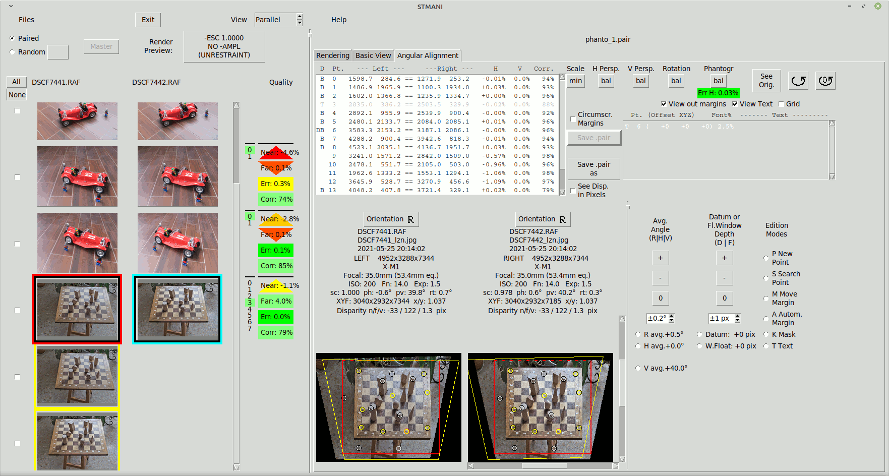
Rendering can also be done interactively in the "Rendering" tab of Stmani3.
This is explained in Interactive Rendering
For understanding what rendering does it is better to consider a few examples:
Example - 55" 3DTV"#
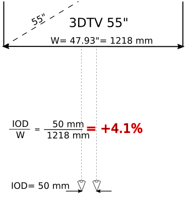
In this example we want to show the images in a 3DTV of 55". The spectator closest to the screen is at 2.5m
The image must fit in the 16:9 aspect ratio of the 3DTV. There are several options to do this that are
explained in Size Prescriptions, but in this example
we will generate the image to its maximum possible size, and make the width to be equal or less
than aspect ratio 16:9. This coded -rat 16M:9E ("-RATio 16Maximum : 9Exact")
In the other hand we do NOT want the furthest point to force diverging the eyesight of spectators. We consider 50mm as a worst case ocular distance (typical for children). This means the maximum Far disparity (relative to the screen size) must be 50mm/1218mm= +4.1%
The limits for Near disparity are more elastic, but the famous 1/30 rule gives a clue. This rule is advised for ortho-stereo photos that reproduce the human vision. My interpretation of this rule is that 1/30 radian is a comfortable eyesight convergence angle for most persons. For sure it is possible to converge more, some people even much more, but the larger the angle the more people will find the vision uncomfortable.
So to stay on the safe side we want to limit the convergence of the eyesight to 1/30 radian. For the spectator placed at 2.5m from the screen, assuming the same 50mm IOD, the following graphic shows that the negative disparity must be -2.7%:
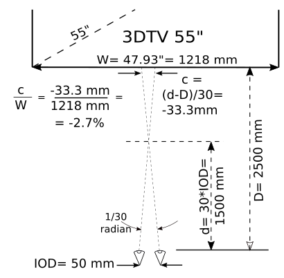
However for Near disparity the worst case is not an small 50mm IOD. It is safer to consider the larger IOD of adults ~65mm. The general formula for the Near disparity with the limit of 1/30 radian is:
$$\frac{IOD - \frac{D}{30} }{W} \;\;\;\;\; (1)$$#
For IOD= 65mm the negative disparity would be -1.5% Therefore we set the disparity prescriptions: -disp 4.1M:-1.5M
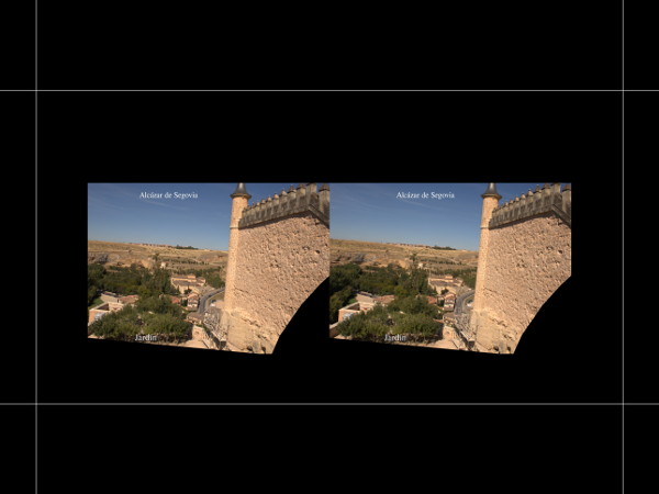
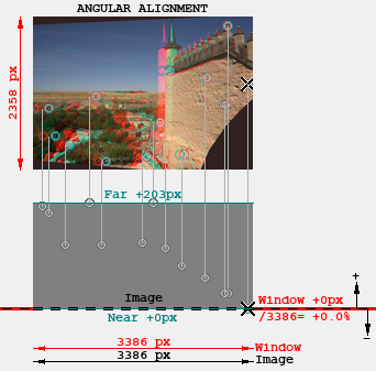
The following graphics show the effect of the size and disparity prescriptions above. These graphics are a sort of "Plan & Elevation" of the stereo images. The lower part in Gray shows the stereo scene and matching points "seen from above", where the lower part is nearest to the spectator. The following terms are used:
- Screen: This the frame of the device where the stereo image is to be shown, e.g. the 3DTV screen, beamer screen, the paper where photos are printed, et al. The Screen is the reference of depths, therefore it is always at zero depth.
- Image: The image file generated in the rendering process. This is normally equal or smaller than the Screen, except when rendering with Canvas Increment. It is also at zero depth, same as Screen.
- Window: This is the useful part of the image, equal or smaller than Image. It may be at the same depth than the Image, or in front of it in case of Floating Window.

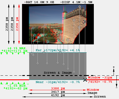
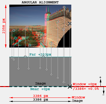
The graphic at the left shows the Angular Alignment image, where Image and Screen are the same thing. In this example the Datum is at zero depth (same as the Image), and it is not defined any Floating Window, therefore the depth of the Window is also zero.
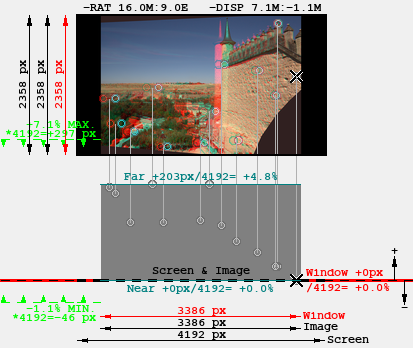
The graphic at the right shows the rendered image. Notice these changes respect the Angular Alignment one:
- The Image does not fill all the width of the 16:9 Screen, because the size prescription was
-rat 16M:9E. If it had been-rat 16F:9Ethen the Image would have filled all the width, filling the empty areas with black. - The Angular Alignment image had a Far disparity of +203px. As the Screen width is 4192px the relative Far disparity would be +4.8% positive, which is more than the pre-scripted maximum of +4.1%. This is corrected by moving the images nearer to each other by 4.8%-4.1%= 0.7%, which makes the disparity of all points more negative. The Far point will have exactly the pre-scripted +4.1% disparity, and the Near point disparity will have -0.7%. The Near disparity is still within the -1.5% prescription but it may produce a Window Violation, which is avoided creating a Floating Window of -0.7% depth. The Floating Window is created by masking a band of 31px width (equivalent to -0.7% of Screen width) at the right of the right Image, and another one at the left of the left Image.
Example - Large Screen#
In this example we want to use an HD 16:9 beamer to project in a 4m wide screen. We assume the closest spectator to be at 5m distance.
The image must fit in the 16:9 aspect ratio of the beamer. The beamer has no zoom facilities, so it does not make sense to render
images to the maximum size (as was done in the previous example). In the other hand we are not sure whether the beamer will support
images with sizes different from 1920x1080px, so we will render to this exact size. This is codified as -pix 1920F:1080E
("-PIXels 1920 Fixed : 1080 Exact")
For the disparity we will apply the same criteria an in 3DTV 55 Example, but restrictions
change in this case because of the wider screen:
For the Far disparity we also consider a worst case IOD= 50mm, which involves
a maximum disparity of 50mm/4000mm= +1.3%
For the Near disparity the IOD= 65mm, the convergence angle= 1/30 radian, and the 5m distance involve -2.5%
(see formula (1) in the 3DTV example)
So the disparity prescriptions are codified: -disp 1.3M:-2.5M. We get the following rendering:
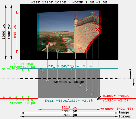
Observe that rendering has met rigorously the +1.3% -2.5% limits, BUT it has been at the cost of shrinking the scale of the image,
which is why it does not fill the 1080px height.
The shrinking has been forced because the total disparity, if unchecked, would be 203px/(2358px*16/9)= 4.8%, which is larger
than the allowed range of +1.3% -2.4%. Therefore it is not possible to meet the prescription only by displacing the images.
¿Could we force some eyesight divergence to the spectators to increase somewhat the Far allowance? Some studies say 1° divergence is acceptable (1/57 radian). Another say the maximum acceptable divergence is 0°. I lean to this last, also calculated for IOD= 50mm because there could always be children around.
Another way to increase the disparity allowance would to increase the minimum distance to the screen (this would increase the minimum Near disparity).
One conclusion of this is that total disparities above 3.7% are not optimal for the 4m screen of this example. In general the larger the screen the less tolerance for excessive disparity.
Observe the following effects in the rendered images:
- Size shrinking, to meet disparity prescriptions as explained before
- The 1920x1080 Screen frame is fully filled with image (albeit with many black areas), because of size
prescription
-pix 1920F:1080E - The images have been displaced 48px towards each other, and a Floating Window has been set at the same -48px depth to avoid Window Violations. This makes most of the image to appear "in front" of the Screen
Example - 5.5" Auto-Stereo#
This is the case of the small screen of an auto-stereo phone that is held in the hand, therefore viewed from a quite short distance ~300mm. We will consider the Elephone P8 3D that is ~121.6mm wide.
Same as the 3DTV case, the image must fit in a 16:9 aspect ratio, and we also want the maximum possible size because
we use the excellent sView app that allows zooming very nicely. Therefore we set the
same size prescription as the 3DTV: -rat 16M:9E ("-RATio 16Maximum : 9Exact")
For the disparity we also want to enforce the 1/30th rule. But in this case the eye-sight converges a much bigger angle just to view the hand held device (which by definition is zero disparity): for 50mm IOD the zero-depth convergence is 50mm/300mm= 1/6 radian, which is a much larger angle than 1/30 radian:
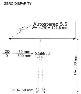
This implies that the Far point should NOT be seen with parallel eye-sight because then
the diference Far-Screen would be 1/6 radian which is too large to fuse comfortably.
In this case the 1/30 radian allowance should be applied AROUND the zero-depth convergence of 1/6 rad. In this situation it is better
to place all or most of the scene behind the screen, mainly because the initial eye convergence is already quite high to increase it still
more by placing the scene in front of the window. We choose to set for the Far point 0.028rad that is most of the total 1/30th, and allow
an small -0.005rad to allow some amount of "pop-out" for the Near point if need be (if the pop-out effect is defined in the
Angular Alignment).
The following graphics show the convergence and disparity for the Far and Near point:
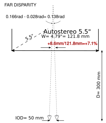
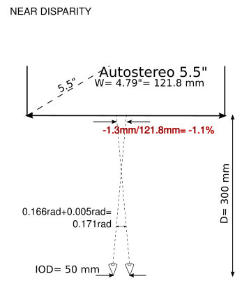
From these graphics we get the disparity prescription -disp 7.1M:-1.1M. We get the following rendering:
Observe that this time the prescription limits +7.1% -1.1% are much wider than image disparities, therefore there
was no need to displace nor shrink the image. The Window remains at the same zero depth as in the Angular Alignment.
This shows that these small auto-stereo devices are best for watching stereo pairs with large disparities.
Example - "OWL" Cards#
The "OWL" is a lens viewer, similar to the old "Holmes". see "OWL"
The features of this viewer:
- Card size: 178x95mm
- Focus distance (adjustable) 125mm - 160mm
- Distance between lens centres: 78mm
- Height of the lens center respect the card: 40mm (a little below the card center at 95/2= 42.5mm)
- Non visible area of the card: 2mm in the lower part
- Lens diameter: 33mm
The maximum width of the images is defined by the distance of the lenses: 78mm. The height would be in theory twice the height of
lens respect the card less the non-visible area of the card: 2*40-2= 78mm. This is a perfectly square shape ratio so we could
set the size prescription as -rat 1F:1E. However it is more convenient to define it in terms of mm rat 78F:78E,
as will be seen later on Canvas Increment and Cut Lines.
This size prescription "F" : "E" fits the image height and fill or crop in width.
The disparity requirements are shown in the following visualization graphic of the OWL. As it is a lens viewer the IOD of the observer does not affect the disparity because the virtual images are at infinity. Because of this the Far point must have 0.0% disparity as a maximum to prevent eyesight divergence. The disparity for the Near point is calculated by letting a 1/30 radian convergence:
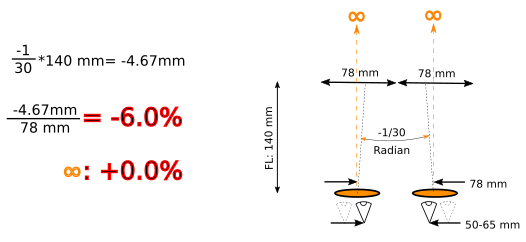
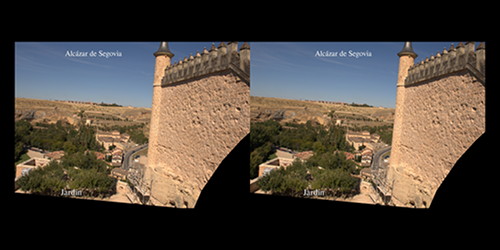
Therefore the Disparity Prescription is: -disp 0.0M:-6.0M The output image that we get:

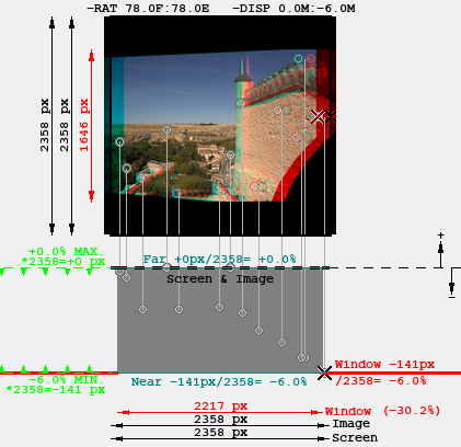
If there were no disparity limitation the image would have filled the height of the screen, and would be cropped in width
because its aspect ratio is wider than the size prescription. But the limitation -disp 0.0M:-6.0M has forced
a shrink to get the Far point at 0% depth and the Near point at -6.0%.
Canvas Increment & Cut Lines#
For printing the stereo card it is necessary to render the image above with the format option -SBS (Side-By-Side) (see Output Options). We would get an image like this:
The trouble is we can not easily print this to get a 178x95mm card with the individual images of 78x78mm
This is solved with the render option -incr (Canvas Increment) that increases the size of the
image without modifying the size of the useful part, such that it matches one of the standard sizes
of photo print services like the 200x150mm that we use for this example.
There is another render option that complements -incr: -lines. This draw guide lines on the
extended canvas to help cutting the card to the desired size. In this example 178x95mm.
The following graphic shows the dimensions of the canvas for printing a size of 200x150mm, with guide lines to cut the card at 178x95mm. Paper margins are shown in blue colour, and guide lines in red colour:

The Incremented Canvas dimensions are defined with the option -incr <left>:<right>:<inside>:<outside>:<above>:<below>
(see Canvas Increment for more detail). In this example: -incr 0:0:0:22:42.5:29.5
The Guide Lines for cutting are defined with a similar option -lines <left>:<right>:<inside>:<outside>:<above>:<below>
(see Guide Lines for more detail). In this example: -lines X:X:X:11:15:2
With these options we get an image file of 5158x3869 pixels, that has the same shape ratio as an standard photo print paper of 200x150mm, so our image will hopefully fit this size. In the other hand it has the guide lines to let us cut the print to get an 178x95mm OWL card: