Angular Alignment#
Stmani3 has two steps of alignment:
-
Angular Alignment: It corrects the pointing deviation of the cameras for the three Euler Angles: Horizontal Perspective (toe in/out), Vertical Perspective (toe up/down) and Optical Axis Rotation. It also corrects small differences from the nominal focal length.
A. Alignment also include the setting of margins for the aligned image. Margins are defined with reference to one of the matching points that is defined as Datum.
A. Alignment does not generate any output image, it defines the parameters to create an ideal stereo pair taken with two ideal cameras with the axis parallel. The transform parameters are stored in a "side-car" text file: *.pair
All these operations are done in the tab "Angular Alignment" in the viewing area. -
Horizontal Alignment and Rendering: This stage applies prescriptions of size and disparity, and then generates the output images in a variety of formats.
The rendering prescriptions do not affect to the Angular Alignment, (see Alignment Quality), but they do affect to the quality indications during A. Alignment because disparities are shown as a percentage of the final viewing screen. For this reason during A. Alignment it is convenient to state the intended size prescriptions using the button "Render Preview":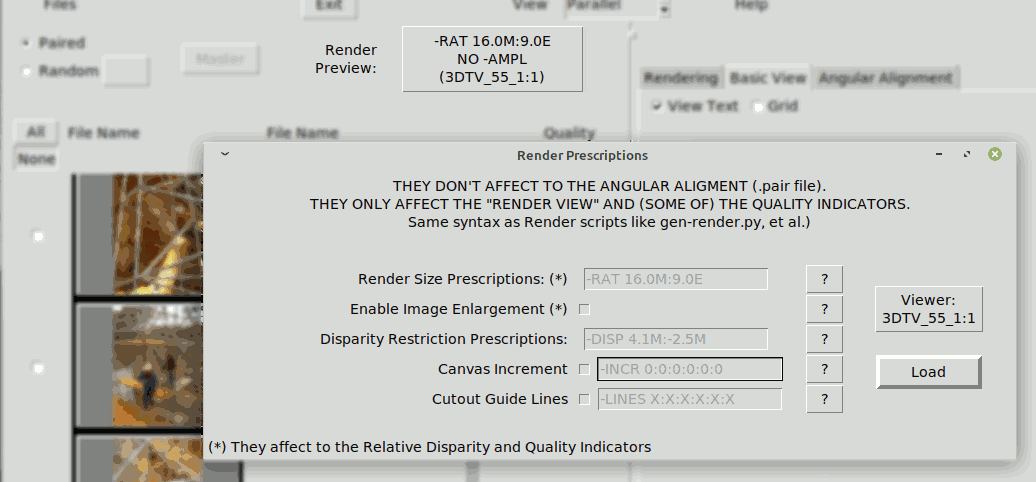
For more details see Rendering
Alignment Elements#
Matching Points#
Angular Alignment is a mathematical computation over a set of matching points, with the goal of reducing the vertical disparity
to the minimum possible value.
It is important that matching points are well determined and cover approximately all significant areas of the scene
in extension and depth.
One of the matching points must be defined as Datum. It is the origin of the margins of the aligned image, and it is also the reference for the disparity of the other points. Because of this the Datum has zero horizontal and vertical disparity, though the horizontal disparity may be set by the user to a value different from zero (see Datum Depth).
It is necessary some amount of Matching Points. The strict minimum would be the number of parameters to solve plus 1 (the Datum).
(see Angular Transformation Parameters), which in the maximum case would be 9.
They could be less than 9 if the alignment is done with less parameters, but this is more prone to alignment errors if only because
some areas of the image may not be covered. It is actually advised to use significantly more than 9 points to improve the alignment quality.
Automatic Alignment#
The Group Option "AUTO ALIGN" makes an automatic search of matching points, and then an automatic alignment of the image pair. There are two way to start the Automatic Alignment:
-
Set of pairs selected with the tick-box, that might be all present if desired. This can only be done in mode "Paired" (see Group Options in Start & Thumbnails). The results are automatically saved in corresponding .pair files.
-
Any single pair of selected images, in either "Paired" or "Random" mode (see Group Options in Start & Thumbnails). The result is not saved automatically, which is told as a warning to the operator.
What if previously aligned#
In case the image pair had a previous alignment, the following criteria are applied:
- Previous Angular Parameters: They are used as initial values for the iterative calculations of the new alignment (see successive approximations)
- Previous Matching Points: They are not kept in the new alignment, but help the search process telling the matching areas of the photo pair. In some cases it is mandatory to provide at least one manual matching point to tell what the matching areas are, as happens for example in Stereo Card Scans
- Margins: The sides that are not automatic are kept and used to limit the automatic point search area.
- Masks: are eliminated
- Texts: They are all associated to the new point "0" (therefore they will change place and should be reviewed afterwards)
Quality of Automatic Points#
Stmani3 uses the ORB & BFMatcher algorithm of OpenCV to find a set of matching points. It then discards those points that:
- have a bad correlation (less than 85%)
- have a low vertical disparity after alignment
The process works reasonably well when the pair of images is not noisy and is well focused.
However even with optimal photos it often fails to place points on foreground objects, which involves
near objects not being taken account in alignment, which may produce window violation. It also fails to place points in noisy or soft focus areas.
For these reasons the Automatic Alignment of Stmani3 does not always provides a good alignment. Therefore it is advisable to review manually afterwards, most often to add some missing point or trim the margins.
Create Point Manually#
Clicking the "P" key the program enters a "New Point" edition state that sets a point mark in the middle of the display. The mark itself can not move, drag the images to determine the approximately position of the matching point. Dragging the right image both images move. Dragging the left image only the left moves.
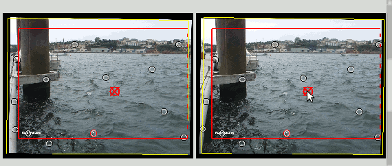
After that the point must be refined and loaded. By right click over the image it opens a "Refine Point" window..
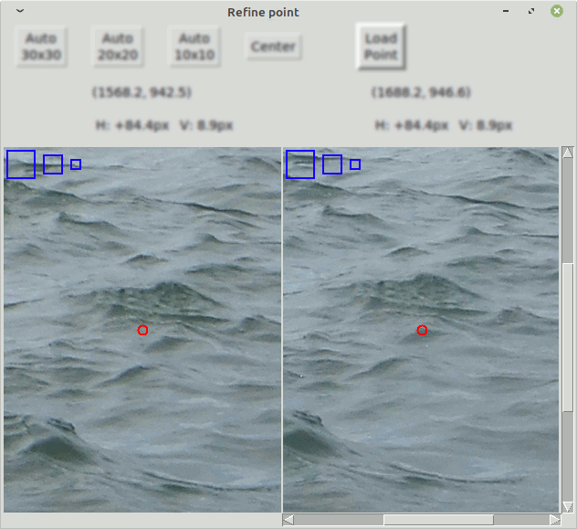
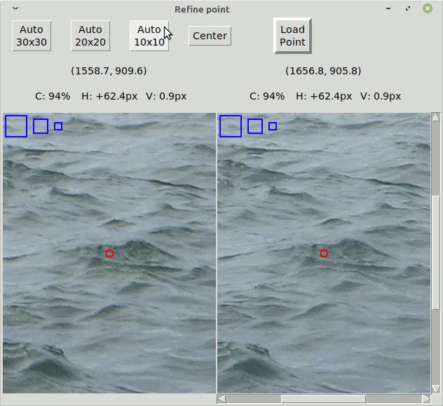
Now place the point approximately in an area with enough contrast in the X,Y directions. Then click one of the buttons "Auto 10x10", "Auto 20x20" or "Auto 30x30". The 10x10, 20x20 or 30x30 are the sizes in pixels of the correlation window that is used to find the best match. The ideal correlation would be 100%. If the correlation is low it may be because the points are not really homologous, it may also happen in blurred images.
The correlation window should only "see" features of similar depth, otherwise it would not get a single matching point, but rather a mess of features from different planes. The small 10x10 window is most useful to find points in thin branches or grasses to avoid picking features behind. The large 30x30 is better for extended blurred areas. The "Refine Point" shows three blue squares to have a sense of the size of the correlation boxes.
If the correlation is good enough, click "Load Point". This will close the refine window and will add the point to the list.
Modify Existing Point#
It should be first selected. This can be done in two ways:
-
Clicking the "S" key the program enters a "Search Point" edition state. The cursor will take a cross shape when the cursor is near enough of a point, then click to select it.
Note the select point operations can only be done on the right image. -
Clicking over one point in the list of points also selects the point.
When a point is selected it changes aspect on the image and is remarked in the list of points.
Point Options#
When right-click over the selected point (over the image or the list of points) there appear a window that offers the following options:
    REVIEW      TRASH      SET     MAKE     PLACE     AS   ASSOCIATE     ASSOCIATE
    POINT                 TEXT     DATUM   IN BASE   TEST    TITLE        TITLE
                                                                          Z-0.2%
- Review Point: Opens a "Refine Point" window that lets modify its position (see Create New Point)
- Trash: Erase the point
- Make Datum: Convert the selected point to Datum.
- Place in Base: Identify the selected point as part of a Phantogram Base (see Phantograms).
- As Test: Excludes the selected point from the Image Aligning, but still shows the H & V disparity.
- Set Text & Associate Title: See Text Edition
Margins#
The margins of the Angular Aligned image are shown with a red rectangle. The position
of each border is initially automatic, to include only the stereo coverage area. However if the option Circumscr.[ibed] Margins is set then the margins adjust to embrace the whole area of both images. This may be useful to avoid unstability in difficult alignment cases.
Borders in automatic mode are indicated with a dashed line.
Clicking the "M" key the program enters a "Move Margin" edition state, which allows moving each of the borders of the margins. The mouse pointer
changes shape when it is near enough from a margin, then the margin can be dragged.
If the margin was in automatic mode it reverts to manual, which is indicated by a continuous line.
To revert a margin to automatic mode click the "A" key, which sets an "Automatic Margin" edition state. Then click near the margin.
Note the margin operations can only be done on the right image.
It is possible to set the margins manually outside the image. The aligned image size will be the one specified by the margins, but the image will show in black the areas outside the images:

Margin Ratio#
It is possible to make the automatic margins to adapt to a fixed form ratio. Set the "Move Margin" edition state with the "M" key and
right-click over any border. A window will appear that let setting a fixed margin ratio.
Only the borders in automatic mode will try to adapt to the fixed ratio, e.g. 16:9, 4:3, et al.
Masks#
This is a complement of the margins intended to hide parts of the image.
Masks are built with a polygon whose vertices are set with the mouse. All vertices are referred to the Datum, same as the margins, therefore they are at the same zero depth
To create a mask polygon or to modify one already existent click the "K" key, which sets a "Mask" edition state.
Note the mask operations can only be done on the right image.
| Click in empy area | Create a new polygonal vertex |
| Click near Vertex | Drag the selected vertex |
| Right-Click near Vertex | Polygonal options: Erase Vertice, Erase All |
In the following image the Mask polygonal hides an object that produces a window violation:
Datum Depth#
The Datum is the reference of the margins, what implies that it has the same depth as them. However it is possible to reference the margins to a "Virtual Datum" at some depth fixed by the user respect the physical Datum point. The effect of this is to have the physical Datum point at some depth respect the margins.
This is done by clicking the "D" key that sets a "Datum Depth" edition mode. Then clicking on the buttons "+", "-" or "0" of the "Datum or Fl.Window Depth (D|F)" will increment, decrement or set to zero the Datum depth. The increment/decrement step in pixels can be modified with the spin-box below.
In the following images the Datum depth has been modified to +128 pixels. The positive value tells it is behind the window. Compare the position of the Datum point (the red point) with the last example of "Mask" where it had zero depth:
Floating Window#
Floating Window is a visual effect achieved by hiding a band at the right of the right image, and another band at the left of the
left image. This produces the impression of having the window nearer to the observer.
The total size of the image is not modified, but the useful image area is narrower indeed. The depth of the Datum
respect the real margins does not change, but the visual margins move forward respect the real ones.
The Floating Window is modified in a similar way as the Datum Depth, only clicking the "F" key instead that sets the "Floating Window" edition mode.
In the following image the Datum depth is zero, but there is a Floating Window at -128 pixels. So the disparity of the Datum respect the window is identical to the case of Datum depth at +128 pixels, The total size of the image is also identical, but the useful width of the image is smaller because of the stop bands at the sides.:
The following LRL's compare the effect of Datum Depth versus Floating Window of the same depth.
NOTE: The depth values in pixels are always respect the Angular Aligned images, not the rendered
ones, which are the ones shown here for reasons of space:
Datum Depth +128 pixel: 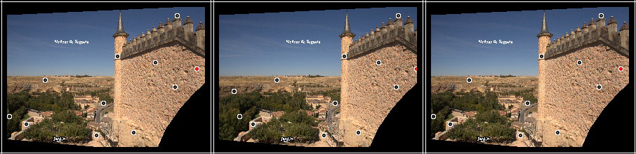
Floating Window -128 pixel: 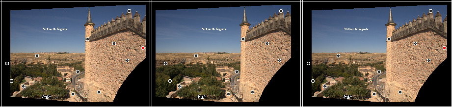
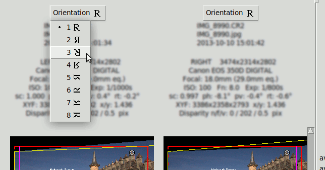
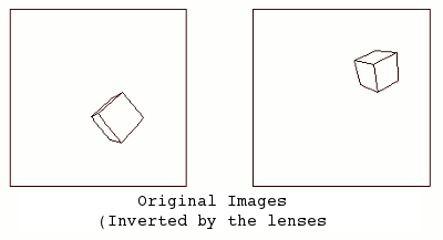
Image Orientation#
Each image has an "Orientation" Button that selects 8 possible orientations:
Angular Transform#
Stereoscopic Photography requires ideally two identical cameras pointing in parallel, such that both sensors lie in the same plane. With this ideal arrangement the cameras would provide two images perfectly aligned, which is to say that they have zero vertical error, i.e. all matching points are at the same height in both images.
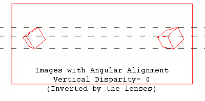
But this ideal condition is rarely met in real stereo cameras. What Stmani3 Angular Alignment does is to
"re-project" the real images taken with a couple of badly pointed cameras, into a single "Virtual Sensors"
plane that must be parallel to the base line linking the focal points of the lenses. In this way we
get the same result as if the photos were taken with a couple of perfectly parallel cameras.
Mathematically this is a Perspective Transformation that converts the couple of real images in
another re-projected couple. The transform parameters are calculated with the goal to minimize the
vertical error in the re-projected images.
The following graphic shows a couple stereo cameras pointing exaggeratedly bad, and the pair of badly aligned images (in black) that are recorded by their sensors. Then it is placed a "Virtual Sensor" plane (in red) that is parallel to the base line linking the lenses, and the images are re projected in this Virtual Sensor using the same objectives:
The Vertical Disparity has disappeared in the Virtual Sensor images:
The mathematics behind this process are explained in this paper at the ReseachGate site:
- ALIGNMENT_OF_STEREO_DIGITAL_IMAGES
Angular Transformation Parameters#
The parameters of the Angular Alignment Transform are calculated automatically as soon as there are enough matching points.
Stmani3 can calculate a maximum of 8 transform parameters, 4 of the left image and 4 of the right one.:
| Left | Right | |
|---|---|---|
| scL | scR | Scale (correction of Nominal Focal Length) |
| phL | phR | Horizontal Perspective or Toe In/Out (rotation in the Y axis) |
| pvL | pvR | Vertical Perspective or Toe Up/Down (rotation in the X axis) |
| rtL | rtR | Image Rotation (rotation in the Z axis) |
Not all parameters are allowed at the same time. In the other hand it is often useful to calculate balanced parameters that reduces two independent parameters into a single one. Each of the 4 basic parameters admits these modes:
- "Scale":
- none Disabled
- min. Calculates only one scL or scR. The one with lesser value
- Horizontal Perspective:
- none Disabled
- bal. Calculates phR, phL as balanced values respect an average value ph0
ph0 is zero by default, but can be modified manually. - indep. Calculates phR, phL independently
- Vertical Perspective:
- none Disabled
- bal. Calculates pvR, pvL as balanced values respect an average value pv0
pv0 is zero by default, but can be modified manually.
- Rotation:
- none Disabled
- bal. Calculates rtR, rtL as balanced values respect an average value rt0
rt0 is zero by default, but can be modified manually. - indep. Calculates rtR y rtL independently
- left Only Calculates rtL
- right Only Calculates rtR
Average Values ph0, pv0, rt0#
The average values are used when the corresponding parameter is in balanced mode. In fact clicking on their controls set the corresponding parameter in balanced mode automatically.
Average values are initially zero. They can be modified manually clicking the "H", "V" or "R" key (for Horizontal persp., Vertical persp. and Rotation), then clicking one of the buttons under "Avg. Angle H|V|R" :
The buttons "+", "-" y "0" are used to increment, decrement or set to zero the average value of the corresponding angle.
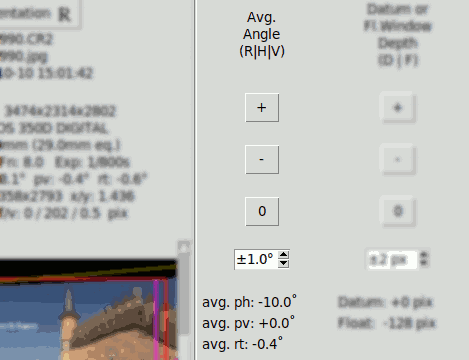
Alignment Results#
The detailed results of the Angular Alignment are shown above the images in the Angular Alignment tab:
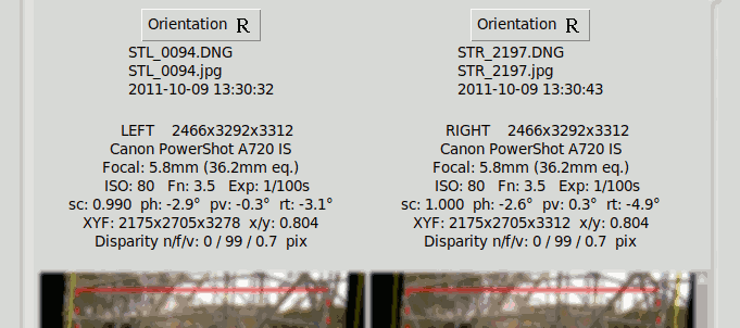
It shows for each image the angular transformation parameters (sc, ph, pv, rt) and the final disparities in pixels: "n/f/v" for Near, Far, Vertical. NOTE these are absolute disparities
Alignment Quality#
A quick indication of alignment quality is provided beside each thumbnail pair, using colours to provide a visual idea of the quality.
Four quality indicators are provided:
- "Near" Horizontal Disparity of nearest matching point
- "Far" Horizontal Disparity of furthest matching point
- "Err." Worst Vertical Disparity
- "Corr." Worst Correlation among left & right sides of a matching point
The disparities shown are percentages of the size of the intended rendering screen, which is specified with the button "Render Preview". Therefore the Far & Near Quality figures change if the rendering prescription change, even though they do not affect to the Angular Alignment and the absolute disparities do not modify. This is shown in the following GIF that shows the effect of toggling between different Render Previews, notice the "Far" indicator changes from 3.7% to 2.1%:
The following is a disparity graphic that shows a sort of "plan & elevation" view of the stereo image. These graphics are explained in Rendering. It is used here to show that the same Far disparity (100px) is perceived differently depending on the intended screen width:
Tips and Tricks#
The Angular Alignment calculation is based on a Least Square method with successive approximations that starts with an initial assumption of the parameter values. If the initial assumption is not too far from the solution the process converges quickly to a good solution. But if they are not the process may not converge, or converge to some local minimum away from the solution. It is also possible to converge to an apparently good alignment (low vertical error), but show an excessively deformed image that does not correspond to the shooting conditions.
Stmani3 starts assuming the focals are equal to the nominal, and all angles are zero. This is good enough
for stereo photos taken reasonably well:
scL = scR = 1
phL = phR = pvL = pvR = rtL = rtR = 0
If the process does not converge properly try the following:
- Avoid setting parameters in "Independent" mode. Using "balanced" mode (or "none") is less likely the alignment to go wild.
- Verify whether all matching points do really match. Look in the first place the points that have a low correlation value and those that show the highest vertical error. Always verify the Datum point (in spite it will always show zero error).
- Make sure the Focal Length is correct, at least approximately. It affects the Angular Transform, more so when the perspective angles are large. If necessary modify the Focal with Group Options
- Modify manually the average value of the parameters (see Average Values), and observe whether the Alignment Quality improves or worsens. Find the avg parameter value that provides the best quality
- Sometimes the margin settings induce alignment unstability. In these cases set all the margins automatic with the option Circumscr.Margins (see Margins)
- Once found average values of parameters that provide a reasonable alignment quality, try setting the parameters again in "Independent" mode. There is now a good chance to converge to a good solution, because the initial assumption is better.
- Sometimes it is not easy to find the initial condition for the successive approximation to converge (this
has a sort of magic:-). However in theory anything can be aligned.
For particularly difficult stereo pairs it helps to have some idea of the shooting conditions: whether a camera is significantly above the other, wildly rotated, et al.
*.pair File#
This file is the only output of the Angular Alignment process. It is a text file with the format of a Python dictionary.
It contains all the necessary data to perform the rendering afterwards.
It is possible to have more than one *.pair file with different parameters associated
to a pair of images. A new *.pair file is produced by clicking the "Save As" button.
This example is from a phantogram image that includes several Base Points and one Test Point:
{'FOTOS': {'der': {'hora': '2021-05-25 20:14:30',
                   'nombre_fich': 'DSCF7442.RAF',
                   'xyf': (4952, 3288, 7344.1)},
           'izq': {'hora': '2021-05-25 20:14:02',
                   'nombre_fich': 'DSCF7441.RAF',
                   'xyf': (4952, 3288, 7344.1)}},
 'REV': '20210714',
 'TEXTOS': [{'borde': None,
             'color': '#FFFFFF',
             'offset': (0, 0, 0),
             'pto': 6,
             'texto': '',
             'tfont%': 2.5}],
 'TRANSF': {'AJUSTE': {'angular': {'der': {'orient': 1,
                                           'ph': 0.0100718684,
                                           'pv': 0.7009470301,
                                           'rt': 0.0057924586,
                                           'sc': 0.9784098646},
                                   'izq': {'orient': 1,
                                           'ph': -0.0100718684,
                                           'pv': 0.6953163715,
                                           'rt': 0.0117340792,
                                           'sc': 1.0},
                                   'pbx': -0.0052229,
                                   'pby': -0.0003711,
                                   'pvo': 0.0},
                       'margenes': {'desv_z': 0,
                                    'float': 0,
                                    'margen_ratio': None,
                                    'origen': (-2008, -2227),
                                    'parche': [],
                                    'pto': 6,
                                    'tamanyo': (3040, 2932)},
                       'permisos': {'auto_margen': {'bottom_side': False,
                                                    'circumscribed': False,
                                                    'left_side': False,
                                                    'right_side': False,
                                                    'top_side': True},
                                    'ph': 'bal',
                                    'phg': 'bal',
                                    'pv': 'bal',
                                    'rt': 'bal',
                                    'sc': 'min'},
                       'ptos_homologos': [{'der': (1271.9, 253.2),
                                           'especial': 'B',
                                           'izq': (1598.7, 284.6)},
                                          {'der': (1100.3, 1934.0),
                                           'especial': 'B',
                                           'izq': (1486.9, 1965.9)},
                                          {'der': (1235.9, 1334.7),
                                           'especial': 'B',
                                           'izq': (1602.0, 1366.8)},
                                          {'der': (2503.5, 329.9),
                                           'especial': 'T',
                                           'izq': (2835.0, 386.2)},
                                          {'der': (2539.9, 900.4),
                                           'especial': 'B',
                                           'izq': (2892.1, 955.9)},
                                          {'der': (2084.0, 2085.1),
                                           'especial': 'B',
                                           'izq': (2480.1, 2133.7)},
                                          {'der': (3187.1, 2086.1),
                                           'especial': 'B',
                                           'izq': (3583.3, 2153.2)},
                                          {'der': (3942.6, 818.3),
                                           'especial': 'B',
                                           'izq': (4288.2, 900.4)},
                                          {'der': (4136.7, 1951.7),
                                           'especial': 'B',
                                           'izq': (4523.1, 2035.1)},
                                          {'der': (2842.0, 1509.0),
                                           'especial': None,
                                           'izq': (3241.0, 1571.2)},
                                          {'der': (2105.0, 503.0),
                                           'especial': None,
                                           'izq': (2478.1, 551.7)},
                                          {'der': (1553.1, 1294.1),
                                           'especial': None,
                                           'izq': (1962.6, 1333.2)},
                                          {'der': (3270.9, 456.6),
                                           'especial': None,
                                           'izq': (3645.9, 528.7)},
                                          {'der': (3721.4, 329.1),
                                           'especial': 'B',
                                           'izq': (4048.2, 407.8)},
                                          {'der': (3000.0, 2776.0),
                                           'especial': None,
                                           'izq': (3265.6, 2838.3)},
                                          {'der': (1037.9, 2762.9),
                                           'especial': None,
                                           'izq': (1261.6, 2792.9)},
                                          {'der': (700.0, 993.0),
                                           'especial': None,
                                           'izq': (898.9, 1011.9)}]},
            'PIL': {'tupla_inv': {'der': (1.1478265063,
                                          -0.2524612779,
                                          726.9477250894,
                                          -0.0052690051,
                                          0.7216380647,
                                          19.9248746777,
                                          -1.755e-06,
                                          -9.95138e-05),
                                  'izq': (1.1543832346,
                                          -0.2588393275,
                                          1042.4926653797,
                                          0.0179052593,
                                          0.7169832364,
                                          40.2617744533,
                                          3.4e-08,
                                          -0.000100186)}},
            'VALOR': {'corr_min%': 79.0,
                      'prl_cercano': -33.3,
                      'prl_lejano': 122.0,
                      'prl_vertical': 1.3}}}