Batch Rendering#
Command Line#
Open a terminal, change to the directory where the photos to process are, and write the command gen-render.py.
The directory must include the photos, the *.pair files generated in Angular Alignment, and at least one
description file *.descr
The synopsis of the command gen-render.py:
python3 gen-render.py <File name>.descr -PIX<Size Prescr.> -DISP<Disparity Prescr.> [Other options]
python3 gen-render.py <File name>.descr -RAT<Ratio Prescr.> -DISP<Disparity Prescr.> [Other options]
python3 gen-render.py <File name>.descr -ESC<Scale Prescr.> -DISP<Disparity Prescr.> [Other options]
It is necessary to supply one *.descr file and prescriptions of size and disparity.
The *.descr is an XML file that tells which *.pair files should be rendered out,
which title if any has each one, and other data applicable to generate photo albums like
HTML5 pages (Overall Title, Author, et al.):
<?xml version="1.0" encoding="utf-8"?>
<presentacion titulo= 'Ejemplo de fichero .descr'
     cabecera= 'Ejemplo'
     pie= 'Autor: A. Fdez. Galaz'
     nombre6= 'STMANI' >

   <pag pair= '20111009_133032_STL_0094_STR_2197' titulo= 'La Gran Dolina' />
   <pag pair= '20131010_150134_IMG_8989_IMG_8990' titulo= 'Alcázar de Segovia' />
   <pag pair= '20140730_181910_DSCF2504' titulo= 'As Veigas' />
   <pag pair= '20160321-132056DSCF50' titulo= 'Valencia,\nJardín Botánico' />
</presentacion>
There are two ways to generate a .descr file:
- In the Stmani3 thumbnail list a subset or all stereo pairs can be selected, then use the
command "GEN. DESCR" to generate the file (see Thumbnails - Group Options)
- Using the command line gen-descr.py. It generates a .descr file including all .pair files that
are found in the directory. The file can be edited afterwards to erase pairs and modify the titles.
Size Prescriptions#
They can be one of these three types:
-PIX <X>[E|M|F]:<Y>[E|M|F] (pixels)
-RAT <X>[E|M|F]:<Y>[E|M|F] (ratio)
-ESC <Scale> (scale)
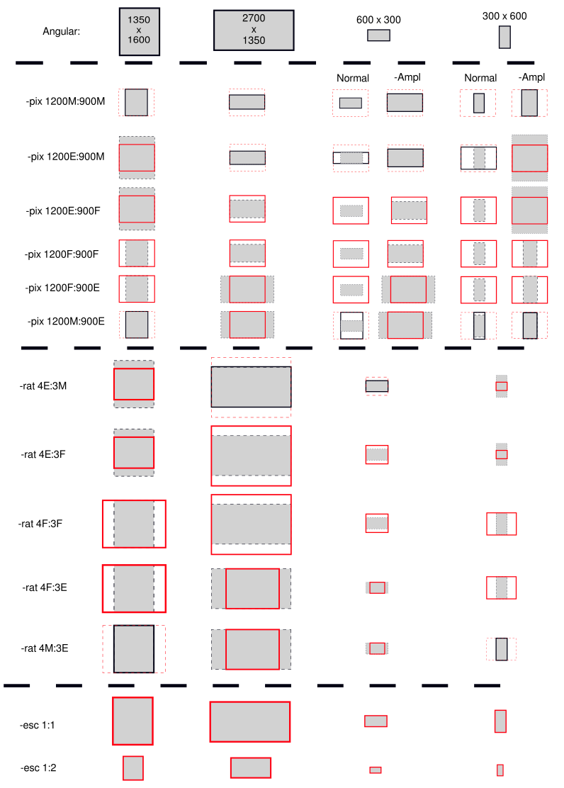
The following graphic description shows how the size prescriptions
modify the ideal image from the Angular Alignment into a rendered image.
Depending on the size of the Angular Aligned image and on the size prescriptions, the
rendered image may adjust exactly to the screen, or may leave some empty space, or may
overflow the screen and crop. Note that:
- The Angular Aligned image is shown in Gray.
- The Rendered image is shown with a thick line frame.
- The screen is shown with a Red frame.
-PIX#
-PIX specifies the size in pixels of each JPG of the stereo pair, or the size of half SBS, or the size of each buffer of an MPO. It must be followed the X , Y size, where each dimension is followed by a letter:
- "F": "Fixed" The output dimension keeps as specified. The image shrinks to adapt to it,
unless:
- The other dimension were "E" (Exact), in which case the image may overflow the dimension or not fill it
- The other dimension were "F" also, in which case the image shrinks enough to inscribe inside both dimensions
- "M": "Maximum" The image shrinks to keep this dimensions equal or less as specified.
- If the other dimension is also "M", it shrinks enough to inscribe inside.
- If the other dimension is "E", the "M" dimension will have the resultant value, except if it is larger than specified, in which case it is cropped.
- "E": "Exact" The image shrinks to equal to this dimension.
- If the original size is less it should be enlarged, but it does not (remaining the same size) unless the option "-ampl" is present.
NOTES: When both options are "F", the images inscribe within the specified size
By default the image could only shrink, not enlarge, unless the -ampl option is set
The pixel values must be integers.
A few examples:
-PIX 700E:800M (typical for 1/2 JPS for a HTML5 viewer)
-PIX 900E:1200F
-PIX 900F:1200F
-PIX 1920F:1080E (typical for a 3DTV with exact size)
-PIX 3840M:2160M
-PIX 800M:480E (typical for W3 display)
-RAT#
-RAT Specifies the aspect ratio of the output JPG's, or half JPS, or each buffer of an MPO. Each component (numerator & denominator) must be followed by one letter "F", "M" or "E", similar to the option "-PIX".
-
If one component is "E" (Exact), the other component would be cropped if its resulting size were larger than the ratio. If its size resulted less, then the action would depend on whether it is "F" or "M":
- If it is "F" the image is generated with the prescribed ratio leaving empty stripes.
- If it is "M" the image is generated with its size, modifying the prescribed ratio.
NOTES: When both options are "F", the frame of the images is circumscribed around the image.
The numerator and denominator values may be integer or real numbers.
A few examples:
-RAT 3.0E:4.0M
-RAT 3E:4F
-RAT 3F:4F
-RAT 36F:24E (typical for 35mm slides)
-RAT 16M:9E (typical for maximum size on any 16:9 viewer)
-ESC#
-ESC Specifies the scale of output photo respect the original.
It is a single real number value. Example:
-ESC 0.5 (output photos are half size of originals)"
Disparity Prescriptions#
-DISP <Far>M:<Near>M
-DISP <Far>E:<Near>M
-DISP Specifies restrictions to the horizontal disparity for the Far and the Near points. See a graphic explanation of Disparity Prescriptions
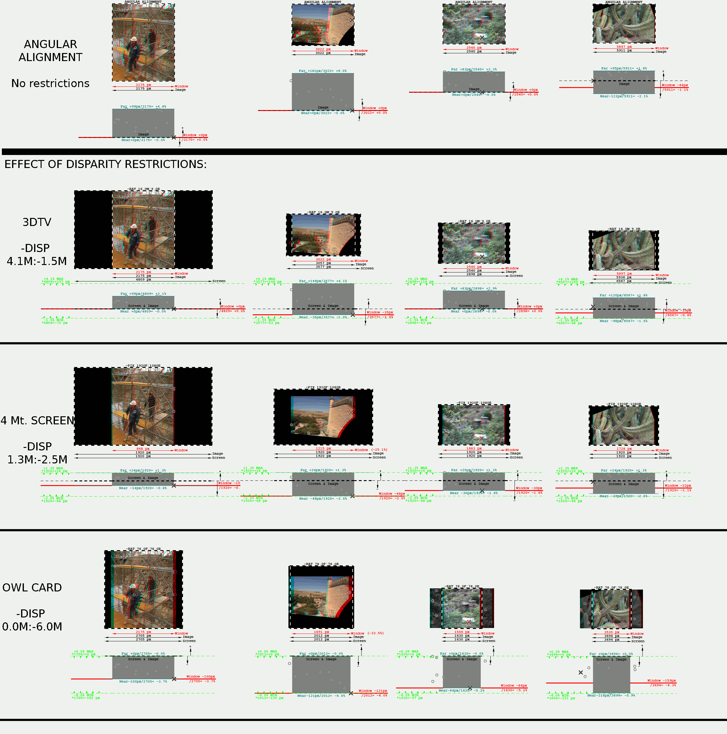
- The numeric values of "Far" and "Near" are percentages of the width of the intended screen (regardless whether the image fills it or not).
- Positive disparities apply to points (usually far) which appear to the viewer behind the window.
- Negative disparities apply to points (usually near) which appear to the viewer in front of the window.
- Far disparity value may have an "M" (Maximum), or an "E" (Exact).
- Near disparity value must only have an "M" (Minimum).
- If Far disparity is larger than the specified Maximum, the images are displaced inwards.
- If a Far Exact value is specified and Far disparity is lower than that, the images are displaced outwards to meet the value.
- If Near disparity is more negative than the specified Maximum, the images are displaced outwards.
- If Near and Far limits were impossible to meet at the same time, then the image would shrink until both ends meet.
A few examples:
-disp 6.71M:-2.0M Far: +6.71% max. Datum-Free Near: -2% min.
-disp 6.71E:-2.0M Far: +6.71% exact Datum-Free Near: -2% min.
-disp 100M:-100M No restriction (Far: +100% max. Near: -100% min.)
Other Size Options#
Image Amplify#
-AMPL It allows the image to increase size (scale > 1), what may
happen with the "-PIX" Size Prescriptions when the image results smaller than specified size.
This is disabled by default.
Canvas Increment#
-INCR <left>:<right>:<inside>:<outside>:<above>:<below>
This does not modify the size of the useful part of the image, but increase the canvas from each border
of the useful image. The incremented area size is filled with Black.
The figures specify the the size of the increment in each border of the image. The units are the ones used
for the Size Prescription (pixels if it was "-PIX", ratio units if it was "-RAT"), they may be integer or real numbers.
It is not compatible with "-ESC" prescriptions.
<left>is the left border of both left and right images. Conversely for<right><inside>is the right border of the left image and the left border of the right image. Conversely for<outside><above>is the upper border of both left and right images. Conversely for<below>
A few examples:
-PIX 900F:1200F -INCR 20:40:0:0:0:0 Provides an image of 960x1200 pixels
-PIX 894F:1194F -INCR 3:3:0:0:3:3 Provides an image of 900x1200 pixels
-RAT 34F:24E -INCR 2.0:2.0:0:0:0:0 Provides an image of 36:24 ratio (a 36mm slide)
Guide Lines#
-LINES <left>:<right>:<inside>:<outside>:<above>:<below>
This draws lines normally outside the useful part of the image but within the canvas enlarged (with the option -INCR). They are intended as cutting guides to trim photo prints into stereo cards of the appropriate size.
The position of the lines is specified in the same way as the -INCR option, that is with reference to the borders of the useful image (before the -INCR increment). The units are also the same as -INCR.
The values are normally positive. Negative values would draw the lines inside the useful image.
The lines can be inhibited by marking them with an "X" instead of a numeric value.
An example:
-RAT 7.7E:8.0F -INCR 0:0:0:1.3:2.5:2.5 -LINES X:X:X:0.6:1.0:1.5 -SBS
In this example the Size Prescription generates an useful image of 7.7:8.0 size ratio, therefore the stereo
pair would have a size ratio of 15.4:8.0
The canvas is incremented in 1.3 in the external lateral borders, and 2.5 by the upper and lower borders,
so the size ratio of the canvas we get is: (1.3+15.4+1.3):(2.5+8.0+2.5)= 18:13.
They are drawn vertical lines at 0.6 from the external lateral borders, 1.0 from the upper border and 1.5 from the lower border, which draws a rectangle of aspect (0.6+15.4+0.6):(1.0+8.0+1.5)= 16.6:10.5
If we take this image to a photo print service and print to a size of 18x13 cm, it would show a guide rectangle 16.6x10.5 cm to help cutting at this size.
Output Options#
Joined Images#
-SBS -SBS50 -MPO -ANA
-OU50 -INTH -INTV
If none of these is selected, it will generate two independent left and right images, with the suffix "_L" and "_R" respectively.
- -SBS Side By Side.
- -SBS50 Side By Side shrunk 50% horizontally.
- -MPO MPO file (Multi Picture Object")
- -ANA Red-Cyan Anaglyph.
- -OU50 Over - Under shrunk 50% vertically.
- -INTH Horizontally Interlaced image.
- -INTV Vertically Interlaced image.
Crossed Images#
-CROSS Crossed images (inverted left and right)
This is only valid with an option of Joined Images
The defaults if this option is not selected:
- -SBS & -SBS50: left and right images at the left and right respectively
- -MPO: left and right images at the 0 and 1 buffers respectively
- -ANA: left image on Red, right image on Cyan
- -OU50: left image up, right image down
- -INTH -INTV: left image on even rows (or columns), right image on odd ones
Rotate Images#
-CW Turn the images 90° clockwise.
-CCW Turn the images 90° counter-clockwise.
This is only valid with an option of Joined Images
Decoration Options#
Text Drawing#
-TEX Writes the image title (if it is defined in .descr), and other texts (if they are
defined in .pair)
The text of the title is defined in .descr, but its position may or not be defined in the
.pair file. If its position is not defined in .pair the title is placed in the lower part
of the window with a default size proportional to the image height.
The other texts have their position and size defined in the .pair file.
Margin Drawing#
-MARG_I <width> Draws a Yellow colour rectangle on the internal margin (the useful
part of the rendered image). It must be followed by the width of the margin in pixels.
-MARG_E <width> Draws a Red colour rectangle on the external margin (all the rendered
image). It must be followed by the width of the margin in pixels.
Matching Points Drawing#
-HOMOP (<digits horizontal disparity>,<digits vertical disparity>) Draws a circle over
each pair of matching points, followed by the value of the horizontal and/or vertical disparity.
It requires two integer numbers separated by a comma, the first for horizontal disparity, the second
for the vertical one.
If a number is zero the corresponding disparity is not printed. If it is larger than zero it tells
the number of significant figures for disparity printing.
NOTE: The two value tuple must not include any space within. Examples:
-HOMOP (0,0)
-HOMOP (2,0)
Pair & Command#
These are two similar options intended for writing some documentation texts over the images:
-PAIR <position>:<font size> Writes the name of the .pair file used
-COMMD <position>:<font size> Writes the command line used
Both options are intended to label stereo images outside the useful image area (in the Canvas Incremented area with -INCR)
<position> and <font size> are defined in the same units as the Size Prescription:
- Pixels, if the size is specified with -PIX
- Ratio units, if the size is specified with -RAT
- It is NOT compatible with -ESC
The origin of <position> is the upper border of the useful image (before the -INCR increase).
The text is placed above the border if <position> is negative.
Note <position> just tells the vertical position. The texts are centred horizontally, and
wrapped if it is necessary. Example:
-RAT 7.7E:8.0F -INCR 0:0:0:1.3:2.5:2.5 -LINES X:X:X:0.6:1.0:1.5 -SBS -PAIR -0.9:0.2 -COMMD -0.6:0.2
Documentation Options#
Documentation Side-Car#
-DOC Creates a text file as a side-car of the generated image. It has the same
name as the image with the extension .txt
This file contains information about the generated image: Used Command Line, Final Disparities,
Alignment Angles, et al.
File Name Options#
Short Name#
-NAME8 Name the output files with 8 characters (for MS-DOS compatibility), composed
with a 6 character prefix followed by 2 figure number that increases sequentially.
The prefix must be specified in the .descr file ("name6" attribute). It is set in upper case
regardless how the .descr file specify it.
If the number of stereo photos to process require more than 2 figures, the 6 character
prefix is truncated 5, to place a 3 figure number.
Numeric Prefix#
-IDX Add a numeric prefix of 2 or 3 figures (as required) to each output file name, to indicate
the order it is placed in the .descr file.
If -NAME8 is present then -IDX has no effect.
Arbitrary Prefix#
-PREFIX <Prefix Text> Add an arbitrary text prefix to the name of the output image. The option is
followed by the text prefix. It is compatible with the option -IDX, but not with the option -NAME8
-prefix '5.5"'
Arbitrary Sufix#
-SUFIX <Sufix Text> Add an arbitrary text sufix to the name of the output image. The option is
followed by the text sufix. It is compatible with the option -IDX, but not with the option -NAME8
-sufix PP3
JPS Extension#
-JPS Set the .JPS extension to the output files. Only with the options -SBS y -SBS50