Phantograms#
Phantograms are a special way to present an image to the viewer. See the Wikipedia explanation
Phantograms are based in a ground plane over which there are pop-up objects, and possibly pop-down holes.
The observer should view identical superimposed images of the Ground Plane that
implies zero disparity, such that the objects above (and holes below) appear to the observer
as if those were real objects placed above or below the surface of the photo print.
The following image is an example:
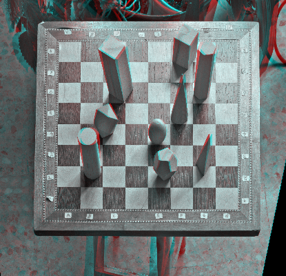
Notice the chess board appears flat without any stereo disparity, same as if it were a 2D image. However there are blocks that appear above and also an scene below.
A phantogram also requires the ground image to have natural proportions. In the example above the chessboard appears square as it actually is. However the photo has to be shot with an angle c. 45° so that the initial image had a perspective distortion. This distortion was corrected to get the natural proportion image shown in the example.
The original perspective is then recovered by the way of looking to the image: This image should NOT be viewed straight on, instead it should be placed horizontally over a table and watched with the same 45° is was taken. This is what produces the phantogram illusion of a real chessboard with pieces above it.
Phantogram Creation#
The following process is intended for horizontal phantograms like the one of the example. It is also possible to make vertical phantograms (i.e. intended to be placed on a wall), but it will be surely more difficult because stereo alignment does not tolerate random setting of Horizontal perspective as it can for the Vertical ones as told below:
- Shoot the image pair with a perspective angle (typically 45°) respect the ground plane. Ideally the Stereo Baseline should be parallel to the ground plane, however Stmani3 can correct small parallelism deviations. The most important requirement is that the ground plane be really a plane.
- Identify the matching points that belong to the ground plane. The Datum point must be one of these to ensure the ground plane had zero disparity.
- Distort the image in Vertical perspective (an horizontal phantogram is assumed), until the initial perspective of the ground plane disappears. This is done by manually varying the average value pv0 (see Average Values ph0, pv0, rt0)
- Make the special Phantogram Alignment as explained below to achieve:
- Minimize the H and V disparities of the ground plane points (their images should become identical).
- The other points should only minimize their V disparity as usual for any stereo image.
- Print the image, place it on a table and watch it with the same angle as it was taken, so the viewer perceives the original scene.
Phantogram Alignment#
As was said the scene must have a base plane. It is important it to be really plane to get the aligned images identical.
First the image pair must be aligned normally:
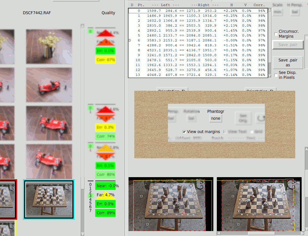
This is an image taken with an V. perspective c. 45°, that includes the necessary ground plane. Notice the Phantogram Alignment enable button is still at none.
Next the points that belong to the ground plane must be identified. This is done with the Point Options:

Now the Base points are shown in yellow on the image, and with a B in the list of points. It is important that the Datum be also a Base point.
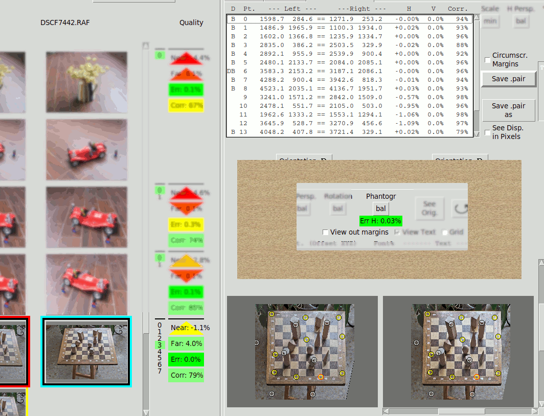
Notice the Phantogram Alignment is still disabled, but below the button it is shown Err H: 2.26% that is the maximum H disparity of the Base points. It is deemed an Horizontal Error because ideally it should zero.
Now see what happens if we enable the Phantogram Alignment:
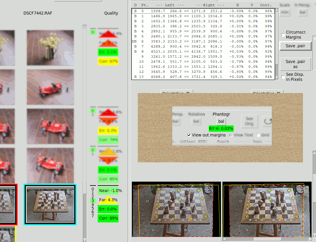
The Phantogram Alignment has reduced Err H almost to zero (0.03% of the image width), so the chequerboard images are essentially identical and have near zero disparity.
However this result is not desirable because the board is obviously distorted. It shows the initial V keystone plus a sort of shear that is the way Stmani3 nulls the H disparity of the ground plane.
It had been better to cancel the Vertical perspective before alignment. So we go back:
Now we apply manually an V perspective that compensates the initial angle as well as possible (see Average Values ph0, pv0, rt0). In this chequerboard example it is possible to visually check when its shape is closer to a perfect square. It is also possible to look for a minimum value of Err H:. Usually the smaller the better.
We arrive to this with a pv0 angle of 40°:
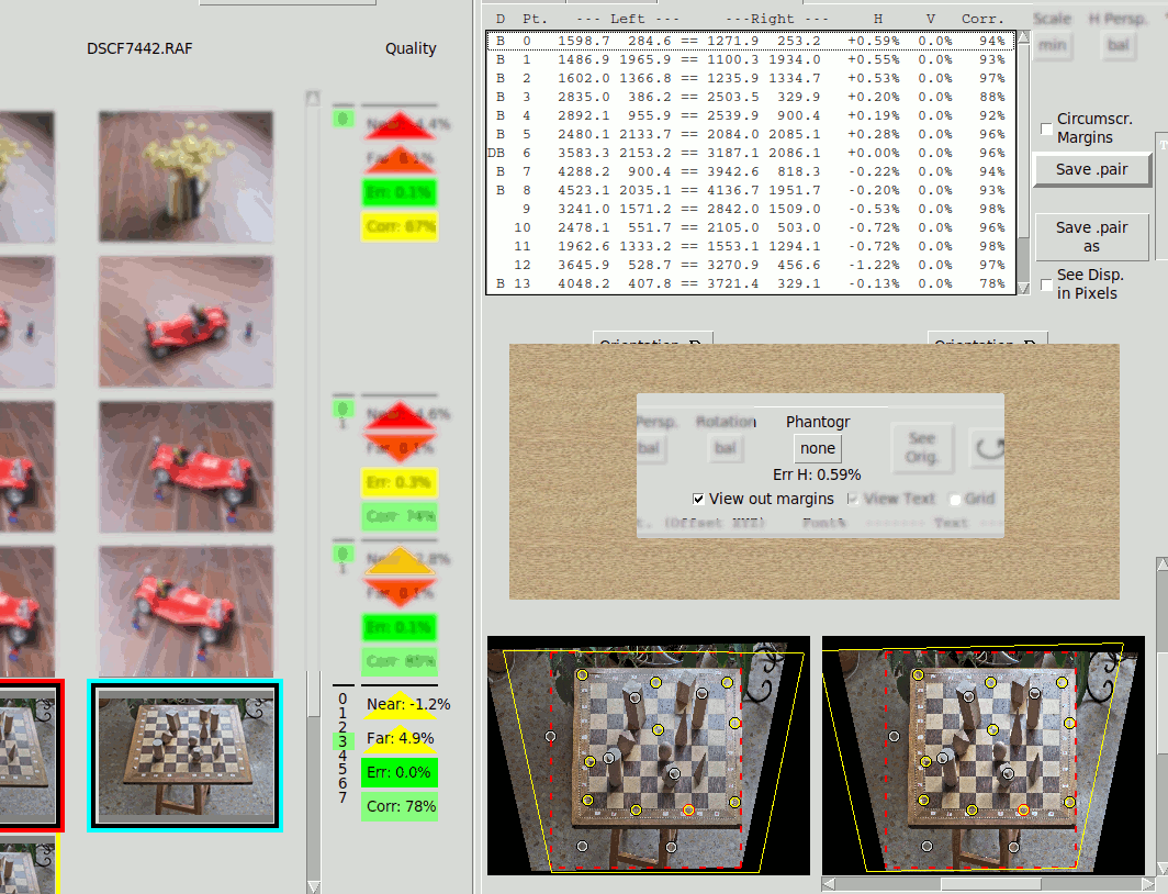
Notice the manual V. perspective as reduced significantly the Horizontal Error: Err H: 0.59% in spite the Phantogram Alignment is still disabled.
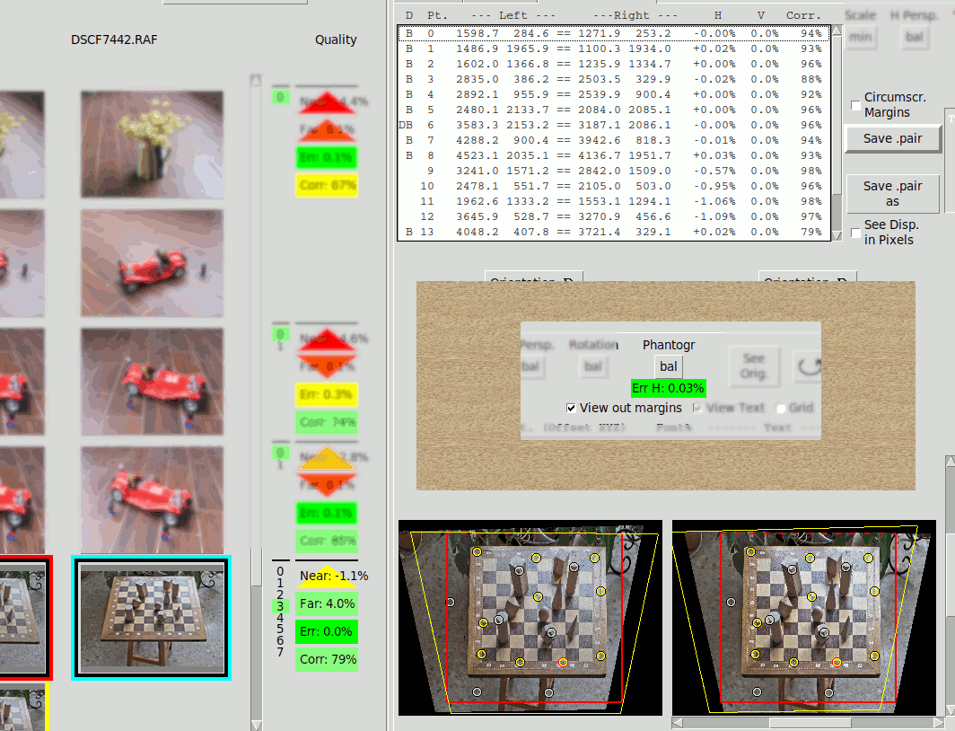
Now we enable the Phantogram Alignment:

The error has been reduced almost to zero. Any residual error is a consequence of the Base Points not being perfectly in a single plane.
We improve a little the margins:
Hiding the outside of the margins we see the final Phantogram: